

合格目指せACP-01101試験最新のACP-01101試験問題集PDF 2023年更新
ACP-01101試験問題集、365日更新無料サンプル
Autodesk ACP-01101認定試験は、AutoCADソフトウェアを使用して設計や図面作成をする能力を証明するための優れた機会です。この認定試験は、AutoCADソフトウェアを使用して正確かつ精密な設計を作成する候補者の熟練度を評価するために設計されています。この認定は、候補者のキャリアの機会を拡大するだけでなく、潜在的な雇用主に対して候補者のスキルと知識を証明するものです。候補者は、実践的な経験を積み、Autodeskのトレーニングリソースを活用して認定試験の準備をすることが推奨されます。
Autodesk ACP-01101認定試験は、製図や設計のためのAutoCADの熟練度を証明したい個人向けの専門レベルの試験です。この試験は、建築、工学、建設(AEC)業界で働くプロフェッショナルや、製造や製品設計分野で働く人々を対象としています。
質問 # 10
With an associative array selected as shown in the exhibit, which command will separate the objects into individual objects?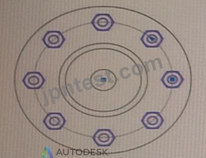
- A. Disassociate
- B. Explode
- C. Break
- D. Ungroup
正解:B
解説:
Explanation
array items are contained in a single array object, similar to a block. You can change the number of these items and their spacing in an associative array.
Based on 2, you can move an item in an associative array by pressing and holding the Ctrl key, and then selecting the items you want to move.
since explode is the command that separates objects into individual objects. Disassociate, ungroup and break are not valid commands for associative arrays.
https://knowledge.autodesk.com/support/autocad/learn-explore/caas/CloudHelp/cloudhelp/2020/ENU/AutoCAD
質問 # 11
In which order should you perform the actions to rotate square (1) to match the angle of square (2).
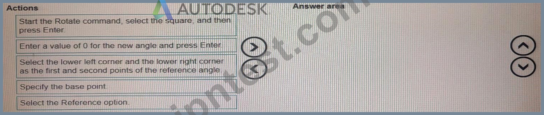
Move all actions to the answer area and place them in the correct order.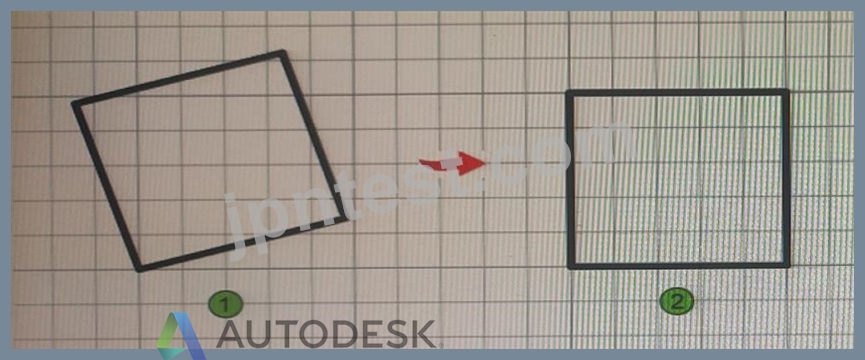
正解:
解説: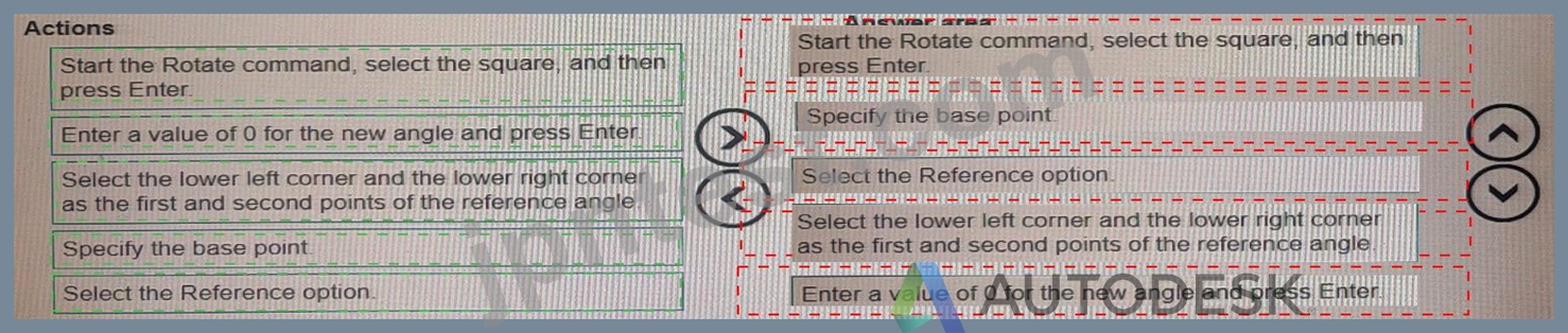
Explanation
rotate is a command that rotates selected objects around a base point to an absolute angle. You can specify the base point and the rotation angle by entering values or selecting points. You can also use the reference option to align objects with other objects.
* 1- Start the Rotate command, select the square, and press Enter
* 4- Specify the base point
* 5- Select the Reference option
* 3- Select the lower left corner and the lower right corner as the first and second points of the reference angle
* 2- Enter a value of 0 for the new angle and press Enter
質問 # 12
Which two objects support associative dimensions? (Select 2)
- A. Hatches
- B. Polylines
- C. Arcs
- D. Images
正解:B、C
解説:
Explanation
associative dimensions adjust to changes in the geometric objects they measure. Dimension associativity defines the relationship between geometric objects and the dimensions that give their distance and angles.
Based on 2 and 3, dimensions in a layout may be associated to objects in model space when the DIMASSOC system variable is set to 2.
質問 # 13
What should be typed at the command line in order to start creating a line for drawing reference that starts at a defined point and extends to infinity in the designated direction?
- A. RAY
- B. CURSORSIZE
- C. XLINE
- D. MLINE
正解:C
解説:
Explanation
According to the AutoCAD for Design and Drafting documents1, the command that should be typed at the command line in order to start creating a line for drawing reference that starts at a defined point and extends to infinity in the designated direction is XLINE2. This command creates a construction line, which is a type of reference line that can help you manage accurate parameters of your drawing2. You can also use point objects as nodes or reference geometry for object snaps and relative offsets3.
質問 # 14
Move three applicable commands from the list on the left to the corresponding function on the right.
Commands may be used once or not at all (Select 3)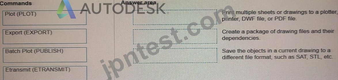
正解:
解説: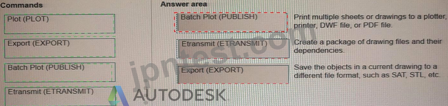
Explanation
Box 1 : Batch plot
One of the topics covered in this course is Plotting Drawings2. In this topic, you can learn how to print multiple sheets or drawings to a plotter, printer, DWF file, or PDF file. The applicable command for this function is Batch plot (PUBLISH)2.
https://www.autodesk.com/certification/learn/course/autocad-drawing-design-drafting-professional Box 2: EtransmitOne of the topics covered in this course is Sharing Drawings2. In this topic, you can learn how to create a package of drawing files and their dependencies. The applicable command for this function is Etransmit (ETRANSMIT)2.
https://www.autodesk.com/certification/learn/course/autocad-drawing-design-drafting-professional Box3: ExportOne of the topics covered in this course is Exporting Drawings2. In this topic, you can learn how to save the objects in a current drawing to a different file format, such as SAT, STL, etc. The applicable command for this function is Export (EXPORT)2.
https://www-int.autodesk.com/certification/learning-pathways/autocad-design-drafting
質問 # 15
You need to change the width of a specific polyline without affecting the width of the other polylines in a drawing.
What should you use?
- A. The PLINEGEN system variable
- B. The PEDIT command
- C. The LWEIGHT command
- D. The PLINEWID system variable
正解:B
解説:
Explanation
polyline is a connected sequence of line segments created as a single object that can contain a width. You can change the width of a polyline by using the PEDIT command.
Based on 3 and 4, LWEIGHT is a command that sets the current lineweight, which is used for new objects and affects objects in the current space only. PLINEWID is a system variable that sets a default polyline width for new polylines. PLINEGEN is a system variable that controls how linetype patterns are generated around vertices.
https://www.roadlesstraveledstore.com/how-do-i-change-the-width-of-a-polyline-in-autocad/
https://knowledgeburrow.com/how-do-i-change-the-width-of-a-polyline-in-autocad/
質問 # 16
You need to create a hatch pattern that looks the same regardless of the viewport scale.
What should you do?
- A. Set the default hatch pattern
- B. Create an associative hatch
- C. Create an annotative hatch
- D. Set the current hatch scale by using the HPSCALE system variable
正解:C
解説:
Explanation
an annotative hatch is a hatch that automatically adjusts its scale and size to match the viewport scale. This means that the hatch pattern will look the same regardless of how you zoom in or out of the viewport.
To create an annotative hatch, you need to:
* Set the annotation scale tool to 1:1
* Create your hatch as usual
* In the properties palette, make the hatch annotative
* Add annotation scales to the hatch as needed
This will create a hatch that displays correctly at different viewport scales.
https://forums.autodesk.com/t5/autocad-forum/annotative-hatch/td-p/2651268
質問 # 17
You are modifying an AutoCAD drawing for a customer.
You would like to bring your customers attention to a specific area of the drawing that you modified for review.
Which type of object is conventionally used?
- A. A solid hatch
- B. A viewport
- C. A revision cloud
- D. A construction line
正解:C
解説:
Explanation
The type of object that is conventionally used for this purpose is D. A revision cloud123. A revision cloud is a way to highlight changes or revisions in a drawing by creating a cloud-shaped polyline around them12. You can create a revision cloud by moving the mouse or by converting existing objects2. You can also change the style, color, layer and properties of the revision cloud13.
質問 # 18
Refer to the exhibit.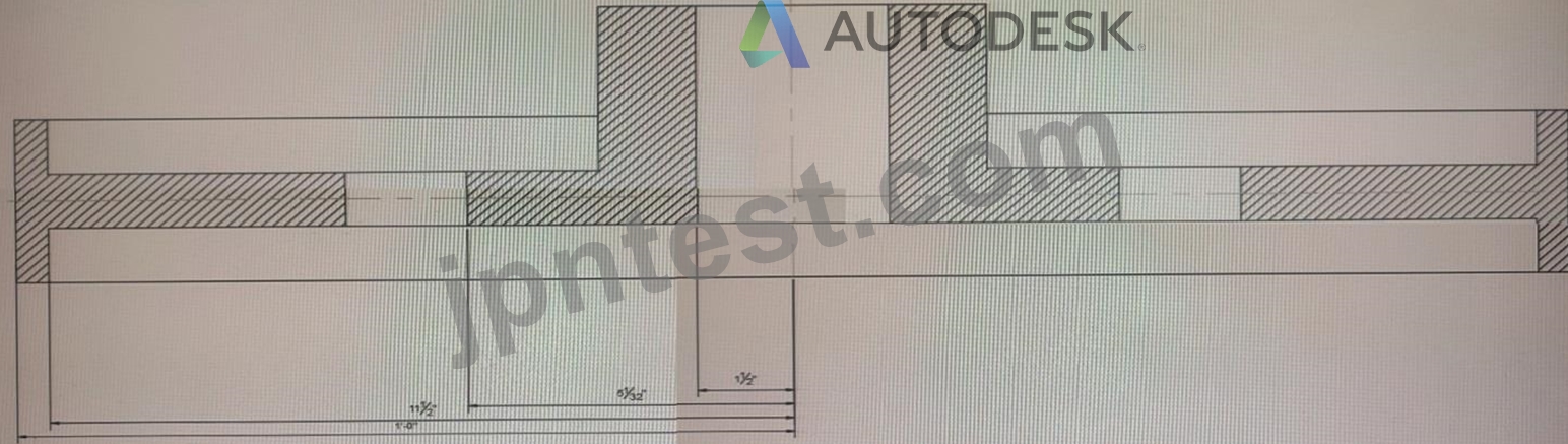
This section view was dimensioned using Baseline Dimensions The dimensions are too close together which impacts the drawing's legibility. What is the most efficient method to avoid this problem in the future?
- A. Dimension Style Manager
- B. Grip Edit
- C. Copy and Paste
- D. Move
正解:A
解説:
Explanation
a baseline dimension is a linear, angular, or ordinate dimension that is measured from the baseline of a previous or selected dimension. The spacing between baseline dimensions can be set from the Dimension Style Manager, Lines tab, Baseline Spacing (DIMDLI system variable).
The most efficient method to avoid the problem of dimensions being too close together in the future is to use Dimension Style Manager. This will allow you to change the default spacing for all baseline dimensions in your drawing.
https://knowledge.autodesk.com/support/autocad/learn-explore/caas/CloudHelp/cloudhelp/2015/ENU/AutoCAD
質問 # 19
Refer to the exhibit.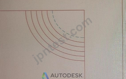
The exhibit shows a set of ornamental garden stairs going up to a walkway as part of a landscaping design.
You need to make sure that the edge of the top step in shown in a different linetype, as shown by the dashed line in the exhibit.
Which prompt in the OFFSET command should you use?
- A. Erase
- B. Current
- C. Source
- D. Through
正解:B
解説:
Explanation
The Current prompt should be used to make sure that the edge of the top step is shown in a different linetype, as shown by the dashed line in the exhibit. This way, you can set a different linetype for your current layer before using the OFFSET command4.
https://knowledge.autodesk.com/support/autocad/learn-explore/caas/CloudHelp/cloudhelp/2021/ENU/AutoCAD
質問 # 20
Refer to the exhibit.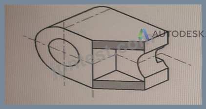
When working on this part created with AutoCAD solids, the dimensions of the shaded planes need to be established.
Which U'CS shows the correct size and shape of the shaded planes?
- A. View
- B. Vertical
- C. World
- D. Face
正解:D
解説:
Explanation
The UCS is a moveable Cartesian coordinate system that establishes the XY work plane, horizontal and vertical directions, axes of rotation, and other useful geometric references1. You can change the UCS origin and orientation for convenience as you specify points, enter coordinates, and work with drawing aids1.
The face option sets a new UCS based on a selected face of a 3D solid object2. This option will align the XY plane of the UCS with the selected face and show its correct size and shape2.
質問 # 21
Drawings from different sources have been combined and resulted in duplicate background elements that are slightly offset from each other Some of the layer names match and other layers have an E prefix, indicating that they are existing.
To clean up the drawing, the Overkill (OVERKILL) command is used.
Which two settings will resolve the duplicate background and offsetting issues? (Select 2)
- A. Ignore Transparency
- B. Maintain associative objects
- C. Ignore Color object property
- D. Tolerance value
- E. Ignore Layer object property
正解:D、E
解説:
Explanation
You need to ignore layer object property to remove duplicates that have different layer names but are otherwise identical4. You also need to set a tolerance value that is larger than the offset distance between the objects5.
質問 # 22
Refer to the exhibit.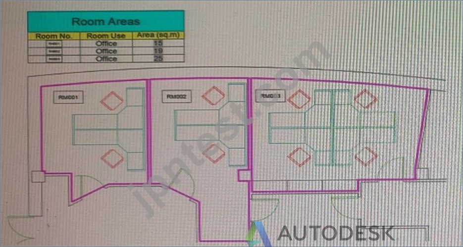
The exhibit shows a plan view of an office arrangement. There is also a table of area of each room areas, which displays the area of each room highlighted with a bold polyline.
The room number labels in the plan are denoted by blocks; made up of a rectangle and a room number attribute.
Which entity in the drawing is used to put the graphical representation of the room number in the Room No.
column in the table?
- A. Rectangle and text
- B. Single line text
- C. Block
- D. Attribute
正解:D
解説:
Explanation
a block attribute is a tag or label that attaches data to a block. The data can be extracted and displayed in a table. Therefore, the entity in the drawing that is used to put the graphical representation of the room number in the Room No. column in the table is B. Attribute.
http://autocadtip.com/how-to-create-block-attribute-in-autocad.html
質問 # 23
Which option of the Array command will distribute items along a path at specified intervals?
- A. Divide Method
- B. Align Items
- C. Measure Method
- D. Associative
正解:C
解説:
Explanation
The option of the Array command that will distribute items along a path at specified intervals is Measure Method1. This method allows you to specify a distance between the items along the path
https://knowledge.autodesk.com/support/autocad/learn-explore/caas/CloudHelp/cloudhelp/2019/ENU/AutoCAD
質問 # 24
You have three multileaders as shown in exhibit 1. (Refer to the exhibit 1 tab.)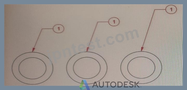
You need to change the display of the multileaders to match the multileaders in exhibit. (Refer to the exhibit 2 tab.)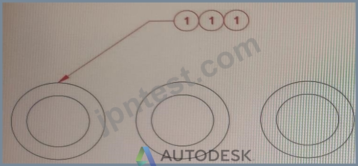
Which command should you use?
- A. Add Leader
- B. Collect Leader
- C. Remove Leader
- D. Align Leader
正解:B
解説:
Explanation
The command that you should use is B. Collect Leader1. The collect leader option groups multiple leaders into one multileader object with a common landing line1. This option is useful when you want to create a single label or callout for multiple objects2.
To use this option, you need to select the MLEADER command and then select Collect Leader from the Options menu. Then you can select two or more existing multileaders that have similar properties and press Enter. The selected multileaders will be collected into one multileader object with a common landing line1.
質問 # 25
You are using the UCS command to set the user coordinate system (UCS)
Select whether each statement is True or False.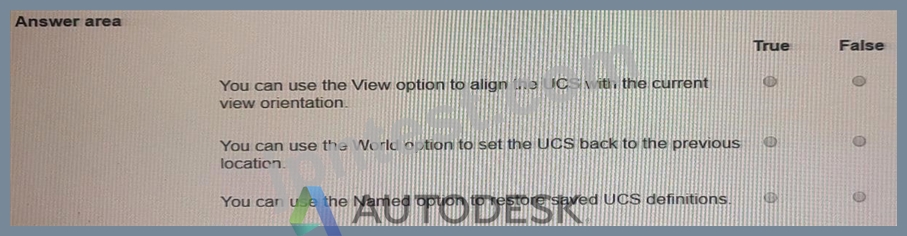
正解:
解説: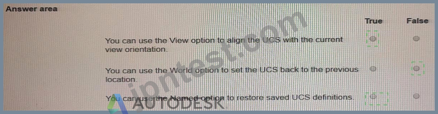
Explanation
* TrueAccording to 1 and 2, UCS is a command that sets the user coordinate system (UCS) which establishes the XY work plane and Z-axis direction for drawing and modeling.
Based on 1, you can use the View option to align the UCS with the current view orientation. This option rotates the UCS so that it matches your current view of a 3D model.
https://knowledge.autodesk.com/support/autocad/learn-explore/caas/CloudHelp/cloudhelp/2016/ENU/AutoCAD
* Falseccording to 1 and 2, UCS is a command that sets the user coordinate system (UCS) which establishes the XY work plane and Z-axis direction for drawing and modeling.
Based on 1, you can use the World option to set the UCS back to its default orientation. This option resets the UCS so that it matches the WCS (world coordinate system).
https://knowledge.autodesk.com/support/autocad/learn-explore/caas/CloudHelp/cloudhelp/2016/ENU/AutoCAD
* TrueAccording to 1 and 2, UCS is a command that sets the user coordinate system (UCS) which establishes the XY work plane and Z-axis direction for drawing and modeling.
Based on 1, you can use the Named option to save or restore named UCS definitions. This option allows you to create custom UCSs and switch between them easily.
https://knowledge.autodesk.com/support/autocad/learn-explore/caas/CloudHelp/cloudhelp/2016/ENU/AutoCAD
質問 # 26
Your company asks you to research alternative editable CAD formats to export to for non-AutoCAD users.
Which three alternative CAD file formats can be exported from AutoCAD? (Select 3)
- A. DWF
- B. IAM
- C. STL
- D. RVT
- E. BMP
正解:A、B、C
解説:
Explanation
https://knowledge.autodesk.com/support/revit/learn-explore/caas/CloudHelp/cloudhelp/2022/ENU/Revit-Docum
質問 # 27
You have the office arrangement shown in exhibit 1. (Refer to the exhibit 1 tab.)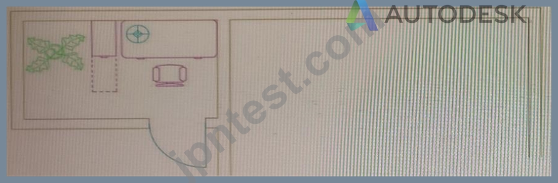
You need a mirror line to create the right-hand office arrangement shown in exhibit 2. (Refer to the exhibit 2 tab.)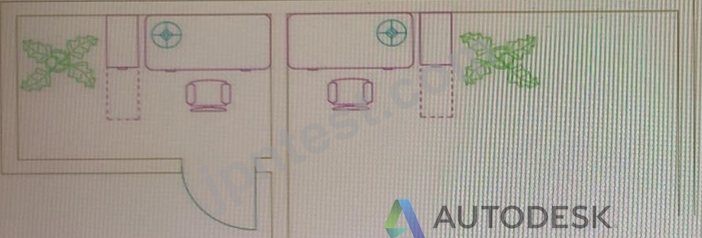
Which tool would you use to make sure the mirror line is centered between the two wall lines without adding additional linework?
- A. Mid Between Two Points (M2P)
- B. Midpoint (MID)
- C. Endpoint (END)
- D. Intersection (INT)
正解:A
解説:
Explanation
https://www.tutorial-autocad.com/mirror-command
http://docs.autodesk.com/ACD/2011/ENU/filesMDG/WS1a9193826455f5ff2566ffd511ff6f8c7ca-3f53.htm
質問 # 28
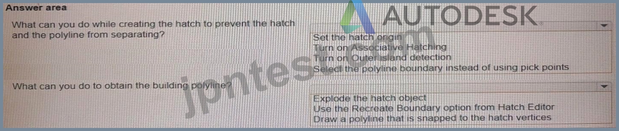
A site plan was recently modified to relocate a building to a new location While relocating the building, only the hatch location of the building was moved by mistake as shown in the exhibit.
Evaluate the graphic and answer each question by selecting the correct options from the drop-down lists.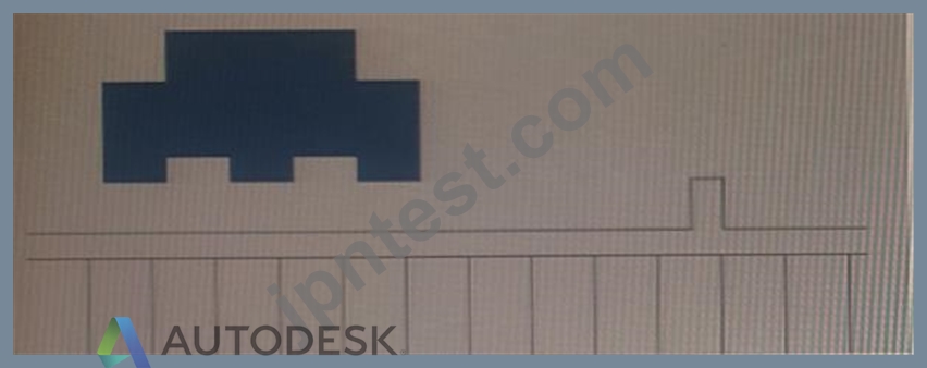
正解:
解説: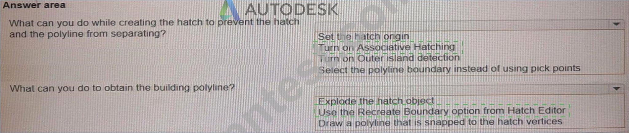
Explanation
Box 1 = Turn on Associative Hatching
Box 2 = use the Recreate Boundary option from Hatch Editor
https://knowledge.autodesk.com/support/autocad/troubleshooting/caas/sfdcarticles/sfdcarticles/Recreating-hatch-
https://knowledge.autodesk.com/support/autocad/learn-explore/caas/CloudHelp/cloudhelp/2018/ENU/AutoCAD
質問 # 29
......
Autodesk ACP-01101認定は、グローバルに認知されており、設計および製図業界でキャリアを向上させたい専門家にとって貴重な資格です。この認定試験は、AutoCADを日常的に使用するエンジニア、建築家、デザイナー、およびその他の専門家を対象に設計されています。この試験は、候補者がAutoCADを効率的かつ効果的に使用し、高品質な設計と図面を作成できる能力を測定します。
ACP-01101問題集、あなたを合格させる認証試験:https://www.jpntest.com/shiken/ACP-01101-mondaishu
まもなくセール終了!リアルACP-01101のPDF解答を使おう:https://drive.google.com/open?id=14whTEWivVCCQ9DN5ufJew73olfMsSCcH